Discover the DDCS Standalone CNC Controller, a cutting-edge solution for CNC machines and routers. This standalone system streamlines your CNC machine operations by directly interfacing with three or four stepper motors, offering an integrated control panel and pendant for enhanced precision and ease of use.
The DDCS controller is an advanced Standalone CNC Controller designed to enhance CNC machine efficiency and precision. Eliminating the need for a computer, it directly interfaces with up to four stepper motors. The package includes a comprehensive control panel and a versatile pendant, facilitating fine-tuned axis movements. It also features a breakout board for easy connection to motor drivers, limit switches, and other peripherals. User-friendly and robust, this controller is ideal for streamlining CNC operations, supporting a range of applications from hobbyist projects to professional manufacturing.
Notes about the different version of this type of standalone CNC controller:
The DDCS V4.1 upgrades from the V3.1 with features like Ethernet file transfer and support for slave axes in gantry machines. It introduces Polar coordinate programming, rotation and radius compensation, and an enhanced motion algorithm for better handling of extensive G-code programs. Other improvements include advanced simulation, alarm inputs, a cycle encoder for the A axis, multi-language support, and refined emergency stop functionalities for safety. This version also incorporates a 32-bit speed generator for improved accuracy and a 7-inch display screen.
The DDCS Expert is a high-performance CNC controller supporting up to 5 axes, with a 7 or 10.2-inch display and a 1MHz output pulse per axis. It boasts an ARM+FPGA design, multiple spindle modes, probe modes, backlash compensation, advanced interpolation algorithms, and supports various CAD/CAM software. This controller is suitable for a range of CNC machines, offering functionalities like high-speed continuous Polyline segment machining, support for large files, and varied user access levels. Its comprehensive features make it ideal for precise and complex machining tasks.
How to use the DDCS v3.1:
This innovative controller is a game-changer, eliminating the need for a computer and CNC interface. It connects effortlessly to four stepper motor drivers and stepper motors, streamlining your CNC setup.
The package includes an intuitive control panel, a versatile pendant for axis movement at three different step increments, and a breakout board. This board simplifies connections to stepper motor drivers, inputs like limit switches and probes, and outputs for controlling devices such as spindles or coolant.
Each axis has its pulse or step signal and direction signal, both positive and negative. Also provided are home, limit minus, and limit plus for each axis. The breakout board and panel's back include essential documentation for connections to drivers, limit switches, outputs, and powering the controller and pendant.
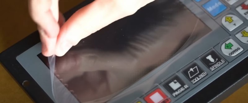
For loading G-code files, a USB thumb drive is included. An extra male-to-female USB cable is also provided for easy access when the controller is mounted.
Now, let's start wiring. The controller and pendant require 24 volts of DC power. For this demonstration, I'm using a 1 amp, 24-volt power supply. Initially, I will connect the power supply to test the controller. However, for a more integrated setup, especially within a cabinet, consider adding a contactor and power button. Detailed wiring instructions for complex setups are available in another video.
The live, neutral, and earth ground wires connect to the power supply. The V+ from the power supply connects to the 24+ terminal and the COM+ terminal, while the V- connects to the Ground terminal and the COM- terminal.
Upon powering up, the main screen displays the digital readout or DRO. Pressing the page R button cycles through three main pages: the DRO, file list, and parameters. In the parameters page, you can navigate through the options using the manual pulse generator on the pendant.
The controller’s parameters are logically arranged in categories, including axis designation, unit settings (inches or mm), and output settings. In the motor parameters section, you'll set the calibration for steps per unit of measurement and axis direction.
Manual control parameters adjust the velocity and acceleration for maximum speed and manual control. Automatic control parameters cover general maximum velocities for G-code processing, default rapid speed, Z clearance height, arc handling, and other miscellaneous settings.
The coordinate system parameters set your work offset, while spindle parameters define M code for spindle engagement, dwell time, default and maximum spindle speeds, and PWM settings.
Home parameters control the speed of homing, signal level, and backoff distance. Probe parameters cover physical sizes, travel speed, probing type, and mode. Hard limit parameters are for setting up limit switches or sensors for each axis, and software limit parameters allow setting travel dimensions for each axis.
MPG parameters include various settings for the pendant, with the last parameter setting the initial state for MPG mode. External button settings pertain to the start, pause, and e-stop buttons.
Backlash parameters offer compensation values with precision to three decimal places. The remaining parameters cover tool offsets and system settings.
To modify a parameter, navigate to it and press enter. Use the arrow keys to move the cursor and modify values.
Now, let's wire the motors and drivers. I’m using two NEMA 23 motors for the Z and Y axes, each with its power supply, set to 2.84 amps. For steps per revolution, I'm setting these to 800 (1/4 microstepping).
The X axis features a NEMA 34 stepper motor, also with its power supply, set to 5.6 amps. For this motor, I'm using 3200 steps per revolution (1/16 microstepping). I’ll demonstrate how to calculate the desired resolution or steps per inch for an axis, using roller chain mechanics as an example.
Now, let's wire the power supplies to the drivers and stepper motors, using 14 gauge power cable. Remember to adjust the input voltage on the power supplies to match your source.
Next, connect the stepper motors to the drivers, using the provided documentation. For the Y and Z axis motors, I'm wiring them in bipolar parallel for higher torque.
I’ll then connect the standalone CNC controller to the drivers, ensuring proper connections for direction and step signals. Testing each motor as I go along helps verify correct setup.
Once the motors are wired, I’ll move on to the inputs, demonstrating both proximity switch and mechanical limit switch connections. Remember to set the appropriate parameters for normally open or normally closed configurations.
That concludes our setup tutorial for the DDCS V3.1 Standalone CNC Controller. This controller offers a streamlined, efficient approach to CNC machine operation, suitable for a wide range of applications.