Printed Circuit Board Isolation RoutingWiring circuits on a perf board, or trying to get a good etch using laser transfer and harmful and messy chemicals can be a challenge. For a while now, I have wanted to start making my own circuit boards with the CNC machine. The other curious thought is, how will PCB fabrication work with my new design for the roller chain drive. From the tests that I have done, the results are impressive and being so overjoyed, I created a tutorial. I also created this tutorial since there are many hit and miss resources out there, so I wanted to offer a place to get a large bulk of the information to give you a running start.
With this tutorial, you will learn the applications necessary for PCB Routing, a primer on these applications (EAGLE and PCB-Gcode), materials and appropriate end mills to remove the copper, considerations for machine setup and the final routing. I will also note the issues that I had during the process.
This tutorial explains the following process:
- The software required to make schematics (EAGLE) and the software required to create the gcode (PCB-Gcode).
- Downloading and installing the software step by step.
- A short primer on using EAGLE with a small Safety Charge Pump as the circuit.
- How to develop a schematic and a PCB layout.
- Important considerations when laying out a PCB to be routed.
- An overview of the PCB-Gcode setup and some examples of what happens to routed boards with various configurations.
- The actual routing of the developed circuit board made in EAGLE with an overview of the end mills needed and considerations for mounting the board and homing.
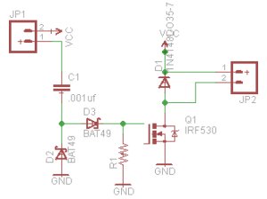
Before we jump right into routing out a pcb, we need to create a circuit. In the video, I go through the composition of a simple charge pump circuit based on the recommended circuit by Mariss Freimanis. This will get you familiar with the functionality of the Eagle application if you are not already (consider this a primer if you are a little rusty). I also recommend a great tutorial by Sparkfun.com here. A charge pump is a circuit to provide safety for unpredictable spindle/router starts or CNC machine behavior while not in Mach3.
Start EAGLE by going through the start menu. Create a new project and name it Charge Pump in the EAGLE control panel by clicking file-new-project. Click on the charge pump project with the right mouse button and select new-schematic. A new schematic screen will appear. The first thing you will notice is a large white area and an extensive set of tools on the left hand side. The tools will allow you to move, copy, add components, add nets to wire everything together, and other tools for creating and modifying schematics. We will need to add many components and connect them together. We will start with GND. To add a component, click on the Add a Part icon on the left. An ADD dialog box will appear. Use the search bar to look for GND. Double click the selection to add the component to the schematic screen. Continue adding components until all of the components are on the screen.
Using a CNC Machine or CNC Router, Printed Circuit Boards can be made using PCB Isolation Routing. PCB isolation routing is a technique that removes copper material to separate or isolate copper fields to serve as wires or traces. In contrast to chemical etching, PCB isolation routing generally removes a minimal amount of copper only to separate the traces.
To get started, we will need to download two different types of programs. First, we will need to get a program to design the circuit schematic and design for the printed circuit board. This program is call EAGLE. The Second program is actually an add-on to Eagle called PCB-gcode by John Johnson. On the main EAGLE page you will see a freeware link. This link will take you to another page to download the freeware version of the program. Once on that page, Scroll down to the download link then select your platform. Eagle is a schematic and printed circuit board design software. Within this software, you will be able to create a schematic from a library of components. These components will be wired together and the printed circuit board can be designed from the schematic. Once the download is complete, execute the setup application and follow the on screen instructions. Now we will download and install the PCB-Gcode add-on for EAGLE. On the PCB-GCode home page, click on the software link in the folder list table. Click on the downloads link which will take you to a list of software versions of the application. Once you get to the page of the selected release, scroll down and click on the download link. The file will come in the form of a zip file. Unzip the file and copy the contents to the ULP folder under eagle folder located within the program files folder. I highly recommend reading the readme file that is located within the zip file.