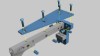
The blackAnt 3D printer uses a process called fused deposition modeling (FDM) and has a much larger footprint than its predecessor. This machine is designed to be mounted onto a wall
the blackant features a Z-axis travel of 771mm (30.35 inches).
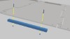
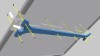
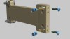
Using seven 1" screws and seven cross dowels, fasten the Z axis rail to the main back of the structure. The screws should be loosely tightened at first.
Repeat the previous step for the opposite side rail. Keep the screws loosely tightened. Once all screws have been loosely tightened, flip the structure over onto a flat surface.
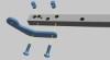
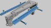
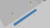
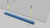
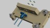
Using 5 1-1/4 x 1/4" screws and 5 1/4" nuts, attach the rail support board to the structure.
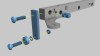
Attach both rail sides to the rail support board using 4 1-1/2" x 1/4" screws and 4 1/4" nuts.
The structure can now be mounted to the wall.
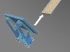
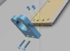
Fasten the angled piece of plexiglass to the board using 2 1" x 1/4" screws and 2 cross dowels.
Attach the piece of plexiglass to the edge of the board using 2 1" x 1/4" screws, 1 cross dowel, 1/4" id bearing, 0.25" ID x 0.37" OD x .03" thickness washer.
Attach the small block of wood to the T-shaped piece of wood using 2 1" x 1/4" screws and 2 cross dowels.
Attach the triangular shaped piece of plexiglass to the top of the board using 5 1" x 1/4" screws and 5 cross dowels.
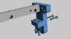
Attach both rail sides using 2 1-1/2" x 1/4" screws and 2 1/4" nuts.
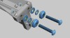
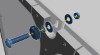
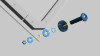
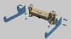
Attach 2 3/8" V Groove bearings using 2 3/8" by 2" screws, 2 3/8" nuts, 2 3/8" ID thin washers and 2 3/8" ID medium washers.
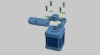
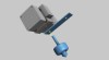
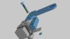
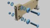
Attach the 5mm ID drive pulley to screw protruding from the center of the 62-oz stepping motor. Then attach the motor to the mounting plate using 4 M3 x 10mm screws and 4 #8 washers.
Attach the 62 oz stepping motor mount using a 1-1/4" screw and 1/4" nut.
Take a 1" x 1/4" screw and fasten it to the bottom of the assembly with a cross dowel.
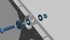
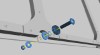
Attach the 3/8" V Groove bearing perpendicular to the screw mounted in the previous step, using a 3/8" x 2" screw, 3/8" nut, 3/8" thin washer, and 2 3/8" medium washers.
Remove the heat block from the extruder. Place the metal plate in between the heat block and the extruder assembly and re-attach the heat block.
Fasten the 1/4"x1-1/2" screw through the acrylic piece and wooden piece to the metal plate with a 1/4" nut.
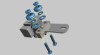
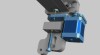
Fasten the two 3/8" V-groove bearings to the extruder assembly using two 3/8" thin washers, four 3/8" medium washers, two 3/8" x 2" screws, and two 3/8" nuts.
Position the extruder assembly (V-Groove bearings) onto the rail.
Secure the extruder assembly onto the arm using a 3/8" V-Groove bearing, 3/8" x 2" screw, 3/8" thin washer, two 3/8" medium washer and 3/8" nut. Position the rails between the V-groove bearing slots and then tighten the nut to secure the V-groove bearings onto the rails.
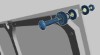
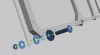
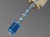
Fasten the bearing system to the plexiglass using a 1/4" x 1/-1/2" screw, 1/4" ID bearing, four 1/4" fender washers,, two 1/4" thin washer (between the bearing), and two 1/4" nuts.
Place a 3/8" washer on the 3/8" screw holding the 3/8" V-groove bearing.
Place another 3/8" washer in the middle where the 3/8" screw is and secure it with a 3/8" nut.
Slide the assembly onto the rails on the mounted structure.
Attach the left-side wooden piece as shown in the image using two 1/4" by 1-1/2" screws and two cross dowels.
Attach the plexiglass piece to the bottom of the left-side wooden piece and mounted frame using two 1/4" x 1" screws and two cross dowels.
Secure the NEMA 17 (62oz-in) stepper motor to the plexiglass piece using four M3 x 10mm screws and four #8 washers
Attach the right-side wooden piece as shown in the image using two 1/4" by 1-1/2" screws and two cross dowels.
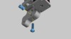
Insert into the square plexiglass piece a 1/4" x 1" screw, two 1/4" fender washers, two 1/4" thin washers, 1/4" ID bearing and 1/4" nut.
Attach the plexiglass piece to the bottom of the right-side wooden piece and mounted frame using two 1/4" x 1" screws and two cross dowels.
Attach timing belt using a #6 x 1-1/2" and a #6 nut. Pictures will be added to describe this process in more detail.
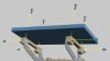
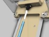
Attach the top plexiglass piece to the top of the unit using twelve 1/4" x 1" screws and twelve cross dowels. The illustration shows the placement for the first 8 screws.
This is a continuation of the previous step, showing the final four screws to make a total of 12.

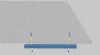
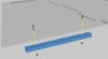
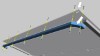
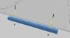
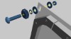
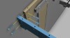
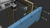
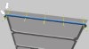
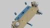
Attach the front plexiglass plate with the 18" piece of aluminum angle to the structure using four 1/4" by 1" screws, eight 1/4" medium washers and four 1/4" nuts.
Attach the plexiglass to the left arm using two 1/4" x 1" screws and two cross dowels.
Attach the plexiglass to the right arm using two 1/4" x 1" screws and two cross dowels.
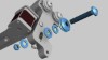
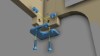
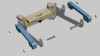
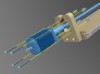
Attach the V-groove bearings to the bracket using two 3/8" x 2" screws, two 3/8" V-groove bearings, two 3/8" medium washers, two 3/8" thin washers, and two 3/8" nuts.
Place two 1/4" x 1" screws with cross dowels in the bracket from the previous step.
Attach the V-groove bearings to the bracket using two 3/8" x 2" screws, two 3/8" V-groove bearings, four 3/8" medium washers, two 3/8" thin washers, and two 3/8" nuts.
Place two 1/4" x 1-1/2" screws with cross dowels into the bottom of the bracket.
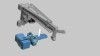
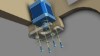
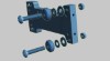
Secure the 1/2" anti-backlash nut to the bracket using two #8 x 1-1/2" screws, two #8 washers and two #8 nuts.
Attach the plexiglass pieces to each side of the bracket using four 1/4" x 1" screws and four cross dowels.
Attach the pieces of wood to the outside of each plexiglass piece using four 1/4" x 1-1/2" screws and four 1/4" nuts.
Attach the base to the arms using four 1/4" x 1" screws and four cross dowels.
Align the V-groove bearings through the rails on the bottom of the structure.
Attach the bottom motor mount onto the back panel of the structure using two 1/4" x 1-1/2" screws and two cross dowels.
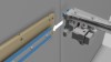
Attach a 1/4" coupling to the motor mount and join to a 1/2" coupling using a coupling spider. Attach the 1/2" coupling onto the 1/2" lead screw.
Align the 1/2" lead screw into the opening on the 1/2" anti-backlash nut.
Attach the NEMA 23 (100oz-in) motor to the bottom base structure using four #8 x 1-1/2" screws, four #8 washers, and four #8 nuts.