Instructions
1
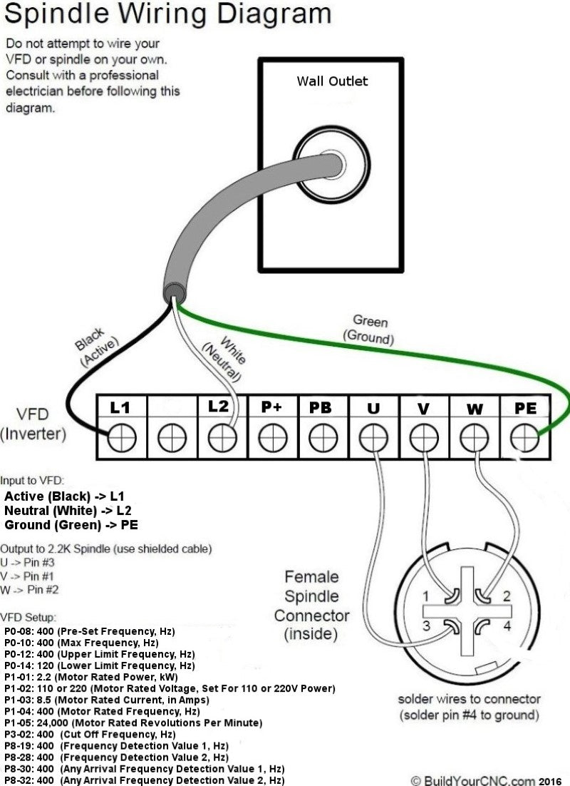
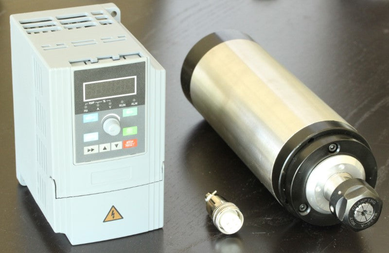
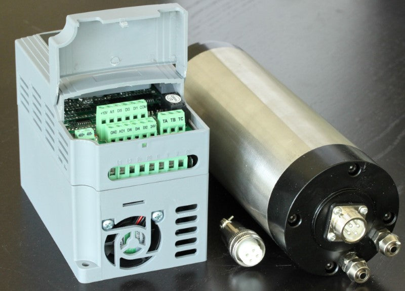
Spindle Wiring Diagram U -> Pin #3 V -> Pin #1 W -> Pin #2 Pin #4 is disabled. How to Program Inverter / VFD When Inverter is first powered on, there should be text flashing on the screen. Step 1: Press "MODE" button. The screen should now say "P0" Step 2: Use the UP and DOWN arrow keys to change the P setting to the desired parameter. Example: To change setting P3-02 use the SIDE arrow to move the cursor. The flashing digit is the one currently selected. Change the digits using the arrows until the screen reads P3-02. Step 3: Press "Enter" to input the parameter for the setting. Example: After you have used the arrow buttons to select your setting, press the "ENTER" button and the screen will now change to the parameter. For instance: Setting P3-02 should be changed to 400.00. Step 4: Change the parameter using the arrows. When you have input the correct parameter, press "ENTER" again to save your setting. 400 Hz is equivalent to 24,000 RPM. It is a linear conversion from 0 to 400 Hz, for instance, 200 Hz is 12,000 RPM VFD Settings: Disclaimer: These values are provided for your convenience. Verify with the values in the manual that came with your VFD. Employ or seek the guidance of a professional electrician experienced in motor, spindle and VFD specifications and operation. THE WARRANTY OF THE SPINDLE AND VFD DEPENDS ON THE PROPER SETTING OF PARAMETERS AND THE USE OF A PROFESSIONAL ELECTRICIAN EXPERIENCED IN THIS TYPE OF OPERATION. I have not thoroughly tested the ranges of all parameters, and cannot vouch for the default values in the VFD that you are using. These instructions are an attempt to assist in cross referencing the parameters of disparate VFDs. To start and stop the spindle under Mach3, use a relay on your interface board (controller, like the Pokeys57CNC, Mach3 USB board, or parallel breakout board) and connect one side of the relay to DCM (XGND on some VFDs) and the other side of the relay to FOR (FWD on some VFDs). If the CNC controller contains more than 1 relay, you can use the relay to start the spindle in reverse mode using the same DCM (VGND) and the REV terminals.
Basic parameters that we recommend setting and confirming for simple control panel operation. Use the parameter that matches your VFD (i.e. PD###, P#-##, P##.##).
- Main Frequency, Hz: In digital operator mode (PD001 set to 0) the VFD/Inverter will run at this parameter value and can be changed at the control panel using the up and down arrows. In multi-speed, this value is the same as Speed 1. If the VFD is set to use the external multi-terminals, then speed 1 will be set by the analog of the external terminals. This parameter value is limited by the maximum operating frequency
- PD003: 400
- P0.00: 400
- Base Frequency/Pre-Set Frequency, Hz
- PD004: 400
- P0-08: 400
- Max Frequency/Upper Limit Frequency, Hz
- PD005: 400
- P0-10: 400
- P0-12: 400
- P0.04: 400
- P0.05 (At Max Voltage): 400
- Intermediate Frequency, Hz. This value coincides with the intermediate voltage related to the ramping up of the spindle. This is to say, at the intermediate voltage (below PD009) of 13V, the intermediate frequency will be 2.5Hz. Be careful with this setting as a frequency too high for the set intermediate voltage can cause the spindle to try to spin up too fast. When the spindle tries to spin up at a higher frequency than the voltage is set, the spindle will draw more current to try to get up to that frequency. That means that you can get an over-current condition and that can also harm the spindle coils (too much current means too much heat equals melting the insulation of the copper wires of the coils, causing the coil wire to short and reducing the resistance of the coil, causing even more current draw, causing lots of smelly smoke and no more cutting of wonderful things).
- PD006: 2.5
- P00.07: 3.5
- Maximum Voltage, V: 220 for a 220 Spindle and 110 for a 110 Spindle. (Check the spindles nameplate or marking for this value)
- PD008: see above
- P00.06: see above
- intermediate Voltage, V: This is at what voltage the spindle will turn at the intermediate frequency setting. If you try to use a voltage setting that causes the spindle to try to spin up too fast, the spindle will over-torque causing an over-current condition. Be careful when setting this value and see the explanation for the intermediate frequency above.
- PD009: 13
- P00.08: 10
- Minimum Voltage, V. This is the minimum STARTING voltage of the spindle and coincides with the lower limit frequency below. See the warning in the intermediate frequency above.
- PD010: 6.5
- P00.10: 5
- Minimum Frequency, Hz. See the warning in the intermediate frequency above.
- PD007: 0.5 allows only a max of 20Hz for this parameter
- P0.09: .2
- Lower limit frequency Hz: This is the control frequency that you want to set to make sure the spindle is not run at a frequency lower than the spindle can handle. All spindles of this nature have a speed (frequency) range that is can safely operate. This is set to 0 since the spindle that you will use may be a spindle that oper ates at a a different range. For example, for a spindle that is sold here, it is safe to run the spindle at 300Hz at the lowest. It may be fine to run it lower but be careful as you may reach the limit of your spindle and the coils will be damaged.
- PD011: 0
- P0-14: 120
- VF Curve Settings: 0-4. For this type of VFD, this is used in lieu of the Lower, and intermediate frequencies and voltages.
- P00.12: 0
- Motor Rated Power, kW
- P1-01: 2.2
- Motor Rated Voltage, Set according to what voltage your spindle/VFD uses
- P1-02: 110 or 220
- Motor Rated Current, in Amps
- PD142: 7
- P1-03: 8.5
- Motor Rated Frequency, Hz
- P1-04: 400
- Motor Rated Revolutions Per Minute, RPM
- P1-05: 24000
- PD144: 3000
- Cut Off Frequency, Hz
- P3-02: 400
- Frequency Detection Value 1, Hz
- P8-19: 400
- Frequency Detection Value 2, Hz
- P8-28: 400
- Any Arrival Frequency Detection Value 1, Hz
- P8-30: 400
- Any Arrival Frequency Detection Value 2, Hz
- P8-32: 400
- Motor Pole Number: Confirm on the motor nameplate for the number of poles on your spindle
- PD143: 4
- Inverter Frequency Standard: 0: 50Hz, 1: 60Hz
- PD176: 1
Parameters for Extended Customization
- Parameter Lock: 0: Invalid, 1: Valid (The parameters will be lock and prevents tampering of the parameter values)
- PD000: 0
- P00.13: 0 (This VFD also includes 10: Restore factory settings)
- For PD### VFDs: Run Control Source (Run Commands): 0: All run commands are controlled by the front panel of the VFD/Inverter, 1: The run commands are controlled by the multi-terminals (the control is by an source like a computer using Mach3 or equivalent control program), 2: Communications port (i.e. a connection from a computer or other device that communicates via RS-245 serial, like an FTDI to USB converter)
- PD001: 0
- For P##.## VFDs: Run Control Source (Run Commands): 0: All run commands are controlled by the front panel of the VFD/Inverter, 1: The run commands are controlled by the multi-terminals (the control is by an source like a computer using Mach3 or equivalent control program), but the STOP key still works, 2: Same as (1) but the STOP key will not work, 3: Communications port (i.e. a connection from a computer or other device that communicates via RS-245 serial, like an FTDI to USB converter), 4: By user application program control electronics.
- P00.01: 0
- Frequency Control Source: 0: Panel (Potentiometer on the front panel), 1: Board or External potentiometer (refer to the PD070-076 for related parameter for controlling the analog input, 2: Communications port (i.e. a connection from a computer or other device that communicates via RS-245 serial, like an FTDI to USB converter)
- PD002: 0
- Acceleration Time: The time it takes to ramp up to the set speed
- PD014, 16, 18 and 20: Specify the longest time that you can allow. If the time is too low, the spindle will draw excessive power and will cause a fault
- Deceleration Time: The time it takes to slow down to the stop or lower limit frequency
- PD015, 17, 19 and 21: Specify your maximum allowable time.
- Reverse Rotation Select: 0: Reverse Run forbidden (will not run in the reverse direction), 1: Reverse Run Enable
- PD023: 1
- STOP Key Select: 0: STOP Invalid (the STOP panel button will be disabled), 1: STOP Enabled
- PD024: 1
- Starting Mode: 0: Start from starting frequency, 1: Frequency track start
- PD025: 0
- Stopping Mode: 0: Deceleration Stop, 1: Coasting stop (prepare to wait for a while for the spindle to stop depending on the condition of the bearings), 2: (Only for P## VFDs) DC Brake Stop (See PD029-31 for DC Braking for the PD### VFDs)
- PD026: 0
- P00.03: 0
- Starting Frequency: 0.1 to 10.0 Hz
- PD027: .5
- Stopping Frequency: 0.1 to 10.0 Hz
- PD028: .5
- Braking Time at Start: 0-25
- PD029: 0
- Braking Time at Stop: 0-25
- PD030: 0
- DC Braking Level: 0-20%
- PD031: 2.0
- Frequency Track Time: 0.1-20.0 Seconds
- PD032: 5.0
- Current Level for Frequency Track: 0-200.0 Seconds
- PD033: 150.0
- Voltage Rise Time during Frequency Track: 0.1-10 Seconds
- PD034: 0.5
- Jogging Frequency: 0-400 Hz
- PD042: 5.00
- S-Curve Time: 0-6500 Seconds
- PD043: 0
Digital Input/Output Terminal Parameters: Set these parameters if you will be connecting digital signals to the terminals to allow the computer or other device to control the VFD/Spindle.
- PD044 - PD049 (Terminals D1-D6): 0: Invalid, 1: Run, 2: Forward rotation, 3: Reverse Rotation, 4: Stop, 5: Forward/Reverse, 6: Jog, 7: Jog forward rotation, 8: Jog reverse rotation, 9: Timer1, 10: Timer2, 11: Reserved, 12: Overheat signal of heat sink or motor, 13: Emergency stop, 14: Reset, 15-16: Reserved, 17: Ramp select1, 18: Ramp select2, 19: Multi-speed1, 20: Multi-speed2, 21: Multi-speed3, 22: High speed, 23: Middle speed, 24: Low speed, 25: PID Start, 26: Reserved, 27: UP function counter, 28: DOWN function, 29: Drawing, 30: Reserved, 31: Counter, 32: Counter reset
- PD044 (FOR/Forward-D1): 02: Forward rotation
- PD045 (REV/Reverse-D2): 03: Reverse Rotation
- PD046 (RST/Reset-D3): 14: Reset
- PD047 (SPH/Speed High-D4): 22: High speed
- PD048 (SPL/Speed Low-D5): 24: Low speed
- PD049 (SPM/Speed Medium-D6): 23: Middle speed
- PD050 - PDPD053 (Terminals Y1, Y2, FA, FC, KA, KB): 0: Invalid, 1: Run, 2: Zero Speed, 3: Fault indication, 4: Braking indication, 5: Set frequency reach, 6: In acceleration, 7: In deceleration, 8: Arbitrary Frequency 1 reach, 9: Arbitrary frequency 2 reach, 10: Motor overload alarm, 11: Over torque alarm, 12: Inverter overload alarm, 13: Counter reached, 14-16: Reserved, 17: Low voltage alarm, 18: Single stage end indication, 19: Process end indication, 20-26: Reserved, 27: Drawing reached, 28: PID lower limit alarm, 29: PID upper limit alarm, 30: Reserved, 31: Braking resistor act, 32: Fan act.
- PD050 (Y1 Output): 01: Run
- PD051 (Y2 Output): 05: Set frequency reached
- PD052 (Terminals FA, FB, FC): 03: Fault indication
- PD053 (Terminals KA, KB): 03: Fault indication
- VO Output: Output of digital frequency signals 0-7
- PD054: 0
- VO Analog Output Gain: 0-100%
- PD055: 100
- Skip Frequency 1, Hz: 0-400
- PD056: 0.00
- Skip Frequency 2, Hz: 0-400
- PD057: 0.00
- Skip Frequency 3, Hz: 0-400
- PD058: 0.00
- Skip Frequency Range: 0.10-10.0
- PD059: 0.5
- Uniform Frequency 1, Hz: 0-400
- PD060: 0.00
- Uniform Frequency 2, Hz: 0-400
- PD061: 0.00
- Uniform Frequency Range, Hz: 0.10-10.00
- PD062: 0.50
- Timer 1 Time: 0-10.0
- PD063: 0.1
- Timer 2 Time: 0-100
- PD064: 1
- Counting Value Set: 00-65500
- PD065: 00
- Intermediate Counter: 0-65500
- PD066: 0
- Analog Input Quantity 1 Regulation Multistage Velocity: 0-100%
- P00.11: 100
- Analog Input: 0: 0-10V, 1: 0-5V, 2: 0-20mA, 3: 4-20mA, 4: 0-10V, stacked 4-20mA Exterior pulse of input
- PD070: 0
- Analog Filtering Constant: 0-50
- PD071: 20
- Higher Analog Frequency, Hz: 0.00-400.00
- PD072: 50.00
- Lower Analog Frequency, Hz: 0.00-400.00
- PD073: 0
- Bias direction at Higher Frequency: 0: Positive direction, 1: Negative direction
- PD074: 0
- Bias Direction at Lower Frequency: 0: Positive direction, 1: Negative direction
- PD075: 0
- Analog Negative Bias Reverse: 0: Not allowable, 1: Allowable
- PD076: 0
- Up/Down function: 0: Not memorized, 1: Memorized
- PD077: 0
- Up/Down Speed: 0: 0.01 Hz, 1: 0.1 Hz
- PD078: 0
Multi-Speeds Operation
- PLC Operation (Programmable Logic Controller Operation): 0: Normal Run, 1: Internal Control 16-Speed, 2: External control 4-speed, 3:External control 8-speed, 4: Drawing, 5: disturbance
- PD080: 0
- Internal Control Multi-Speeds Operation: 0: Stop after running after 1 cycles, 1: Cycling run, 2: Auto-stop after running after 1 cycle (STOP for intervention), 3: Auto-run and cycling (Stop for intervention)
- PD081: 0
- PLC Before 8-Speeds Running Direction: 0-255 (0: Forward, 1: Reverse)
- PD082: 0
- PLC After 8-Speeds Running Direction: 0-255 (0: Forward, 1: Reverse)
- PD083: 0
- Before 8-Speeds PLC Ramp Time: 0-65535
- PD084: 0
- After8-Speeds PLC Ramp Time: 0-65535
- PD085: 0
- Frequency 2, Hz: 0.00-400.00
- PD086: 15.00
- Frequency 3, Hz: 0.00-400.00
- PD087: 20.00
- Frequency 4, Hz: 0.00-400.00
- PD088: 25.00
- Frequency 5, Hz: 0.00-400.00
- PD089: 30.00
- Frequency 6, Hz: 0.00-400.00
- PD090: 35.00
- Frequency 7, Hz: 0.00-400.00
- PD091: 40.00
- Frequency 8, Hz: 0.00-400.00
- PD092: 0.50
- Frequency 9, Hz: 0.00-400.00
- PD093: 10.00
- Frequency 10, Hz: 0.00-400.00
- PD094: 15.00
- Frequency 11, Hz: 0.00-400.00
- PD095: 20.00
- Frequency 12, Hz: 0.00-400.00
- PD096: 25.00
- Frequency 13, Hz: 0.00-400.00
- PD097: 30.00
- Frequency 14, Hz: 0.00-400.00
- PD098: 35.00
- Frequency 15, Hz: 0.00-400.00
- PD099: 40.00
- Frequency 16, Hz: 0.00-400.00
- PD100: 45.00
- Timer : 0.0-6500.0 Seconds
- PD1: 10
- Timer 1: 0.0-6500.0 Seconds
- PD101: 10
- Timer 2: 0.0-6500.0 Seconds
- PD1102: 0
- Timer 3: 0.0-6500.0 Seconds
- PD1103: 0
- Timer 4: 0.0-6500.0 Seconds
- PD104: 0
- Timer 5: 0.0-6500.0 Seconds
- PD105: 0
- Timer 6: 0.0-6500.0 Seconds
- PD106: 0
- Timer 7: 0.0-6500.0 Seconds
- PD107: 0
- Timer 8: 0.0-6500.0 Seconds
- PD108: 0
- Timer 9: 0.0-6500.0 Seconds
- PD109: 0
- Timer 10: 0.0-6500.0 Seconds
- PD110: 0
- Timer 11: 0.0-6500.0 Seconds
- PD111: 0
- Timer 12: 0.0-6500.0 Seconds
- PD112: 0
- Timer 13: 0.0-6500.0 Seconds
- PD113: 0
- Timer 14: 0.0-6500.0 Seconds
- PD114: 0
- Timer 15: 0.0-6500.0 Seconds
- PD115: 0
- Timer 16: 0.0-6500.0 Seconds
- PD116: 0
- Auto PLC Memory Function: 0-1
- PD117: 0
- Over-Voltage Stall Prevention: 0-1
- PD118: 1
- Stall Prevention at Acceleration: 0-200
- PD119: 150
- Stall Prevention at Constant Speed: 0-200
- PD120: 0
- Deceleration Time of Stall Prevention at Constant Speed: 0.1-25.5
- PD121: 5
- Stall Prevention Level at Deceleration: 0-200
- PD122: 150
- Over-Torque Detect Mode: 0-3
- PD123: 0
- Over-Torque Detect Level: 0-200
- PD124: 0
- Over-Torque Detect Time: 0.1-20.0
- PD125: 1.0
- Pulse Counter Memory: 0-1
- PD126: 0
- Number of Auxiliary Pump: 0-2
Water Supply with Constant Pressure
- PD130: 0
- Continuous Operating Time of Auxiliary Pumps: 1-9000 Minutes
- PD131: 60
- Interlocking time of Auxiliary Pumps: 0-250 Seconds
- PD132: 5
- High Speed Running Time: 1-250 Seconds
- PD133: 60
- Low Speed Running Time: 1-250 Seconds
- PD134: 60
- Stopping Voltage Level: 1-150%
- PD135: 95
- Lasting Time of Stopping Voltage Level: 1-250 Seconds
- PD136: 30
- Wake Up Level: 1-150%
- PD137: 80
- Sleep Frequency, Hz: 0.00-400.00
- PD138: 20.00
- Lasting Time of Sleep Frequency: 1-250 Seconds
- PD139: 20
Motor Function Parameters
- Rated Motor Voltage: Set According to Motor Nameplate
- PD141: *
- Rated motor Current: Set according to Motor Nameplate
- PD142: *
- Motor Pole Number: Number of Magnetic Poles. 2.2kW Spindles typically use 4 Poles
- PD143: 04
- Rated Motor Revolutions: 24000
- PD144: 1440
- Auto-Torque Compensation: 3.0-10.0
- PD145: 2.0
- Motor No-Load Current: 0100
- PD146: 40
- Motor Slip Compensation: 0.0-100
- PD147: 0.0
- Auto-Voltage Regulation: 0-1
- PD150: 1
- Auto-Energy Saving: 0-20
- PD151: 0
- Fault Restart Time: 0.2-25
- PD152: 1
- Restart After Instantaneous Stop: 0: Invalid, 1: Frequency Track
- PD153: 0
- Allowable Power Breakdown Time: 0.1-5.0 Seconds
- PD154: 0.5
- Number of Abnormal Restart: 0-10
- PD155: 00
PID Parameters
- Proportional Constant (P): 0.0-1000.00%
- PD156: 100%
- Integral Time (I): 0.1-3600.00 Seconds
- PD157: 5.0
- Differential Time (D): 0.01-10.00 Seconds
- PD158: 0
- Target Value: 0.0-100.0%
- PD159: 0
- Target Value Select: 0: Set by the operator, 1: Set by external terminals (0-10 volts)
- PD160: 0
- PID Upper Limit: 0-100%
- PD161: 100
- PID Lower Limit: 0-100%
- PD162: 0
Communication Function
- Communication Addresses: 0-250
- PD163: 0
- Communication Baud Rate: 0-3
- PD164: 0
- Communication Data Method: 0-5
- PD165: 0
Monitor Functions
- Display Items: 0-5
- PD170: 0
- Display Items Open: 0-15
- PD171: 0
- Fault Clear: 00 10 (01 for fault cleared)
- PD172: *
- Voltage Rating of Inverter: Set according to the model
- PD175: *
- Rated Current of Inverter: Set according to the model
- PD174: *
- Inverter Model
- PD175: *
- Inverter Frequency Standard: 0: 50Hz, 1: 60Hz
- PD176: 1