[ Log In ]
[ Register ]
Spindle/Laser Combo Head 2
Price Options Your Cart
Laser/Spindle Head Combo with 110V Laser Power Supply
$1299.00
Barebones Structure (Wood Pieces and Hardware) - No Spindle or Laser Components
$229.00
Laser Head Combo w/ 220v Power Supply: No Spindle Included
$749.00
Spindle Head Combo - No Laser Components
$849.00
Laser/Spindle Head Combo with 220V Laser Power Supply
$1299.00
Laser Head Combo w/ 110v Power Supply: No Spindle Included
$749.00
Introduction:

This Laser/Spindle Combo Head is designed to add laser functionality to the greenBull CNC machine. It comes included with a 2.2kw Spindle. With the ability to do laser applications and routing at the same time, this Z-axis attachment will make your machine even more capable of doing large and detailed projects without the need to switch to a different machine.

Description:

The Laser/Spindle combo head was designed with the idea that laser engraving and CNC machining could be done by the same machine. The Z-Axis attachment is specifically designed to hold a mounted 2.2kw Spindle and a 40 Watt CO2 laser tube simultaneously.

If you already have a spindle or laser tube and components, then we also offer options to buy the assembly without these parts. We are also offering the barebones (structure and hardware only) if you wish to supply your own spindle and laser equipment. You can specify whether or not you need 220V or 110V power supply for the laser.

Note: Lead screw length for the Z Axis is 16.5 inches. Packing list may saw otherwise.

Video: greenBull CNC machine with the Laser/Spindle Hybrid Head - Basswood Trials

Ask a question about the Laser/Spindle Combo Head for Heavy Duty CNC Kit (greenBull):
Previously answered questions:

Click on the question to reveal the answer.
  • [Laser/Spindle Combo Head for Heavy Duty CNC Kit (greenBull)] What is involved and how long does it take to swap between laser and spindle?

    There is no swapping between spindle and laser. The laser uses a separate output on the controller to be fired. For example, M3 g-code turns on the spindle; M7 g-code turns on the laser.

    Click the link to add information to this solution:
    [436] What is involved and how long does it take to swap between laser and spindle?

--
Instructions
Laser Hybrid Instructional Image 1A

Attach the Spindle top mount to the z-axis back plate using two 1/4" by 1-1/2" screws and two cross dowels.

1
Laser Hybrid Instructional Image 1C

Attach the Spindle bottom mount to the z-axis back plate using two 1/4" by 1-1/2" screws and two cross dowels.

2
Laser Hybrid Instructional Image 1D

Attach the brush mount support to the z-axis back plate using two 1/4" by 1-1/2" screws and two cross dowels.

3
Laser Hybrid Instructional Image 1E

Attach the laser tube top mount to the z-axis back plate using two 1/4" by 1-1/2" screws and two cross dowels.

4
Laser Hybrid Instructional Image 1F

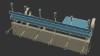
Loosely fasten the z-axis rail and right side rail support piece using six 1/4 x 1-1/2 inch screws and cross dowels.

5
Laser Hybrid Instructional Image 2

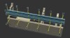
Repeat the process from the previous step for the left side.

6
Laser Hybrid Instructional Image 3

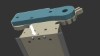
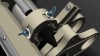
Position the bottom bearing mount on the top portion of the Z axis.

7
Laser Hybrid Instructional Image 4

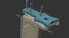
Assemble the z-axis bearing mounts using three 1/4" by 2-1/2" screws and cross dowels.

8
Laser Hybrid Instructional Image 5

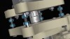
Insert one 1/2" ID (inside diameter) bearing into the bottom bearing mount along with a 1/2" small diameter washer.

9
Laser Hybrid Instructional Image 6

Repeat the process from the previous step over the lead screw protruding from the top of the bearing mount.

10
Laser Hybrid Instructional Image 7

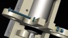
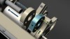
Assemble two of the 1/2" coupling hubs with a coupling spider in the middle.

11
Laser Hybrid Instructional Image 8

Install the flexible coupling (coupler) at the top portion of the lead screw. Make sure that the lead screw has just enough protrusion that it will be flush with the 1/2 coupling hub flat portion and does not protrude so much that the lead screw will interfere with the coupling spider.

12
Laser Hybrid Instructional Image 9

Assemble the motor to the z-axis motor mount using four 1/4" x 1 - 1/2" screws and four quarter inch nuts.

13
Laser Hybrid Instructional Image 10

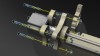
Assemble the motor mount to the top bearing mount using four 1/4" by 2 - 1/2" screws and twelve 1/4" nuts.

14
Laser Hybrid Instructional Image 11

Fasten the 1/4" nuts between the motor mount and the bearing mount to secure both pieces.

15
Laser Hybrid Instructional Image 12

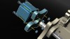
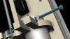
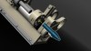
Insert the 2.2 kW Spindle through the top and bottom Spindle mounts.

16
Laser Hybrid Instructional Image 13

Attach the air pump to the back plate of the z-axis using a zip tie.

17
Laser Hybrid Instructional Image 14

Attach the power supply to the right rail support using four #6 by 1" screws, four #6 nuts and eight #8 washers.

18
Laser Hybrid Instructional Image 15

Insert a 1/4" by 2-1/2" screw into the top spindle mount using a 1/4" nut and two 1/4" washers.

19
Laser Hybrid Instructional Image 16

Insert a 1/4" by 2-1/2" screw into the bottom spindle mount using a 1/4" nut and two 1/4" washers.

20
Laser Hybrid Instructional Image 17

Insert 1/4" by 1-1/2" thumb screws through the bottom brush support to attach the brush. The 1/4" insert nuts will be in the bottom face of the brush.

21
Laser Hybrid Instructional Image 18

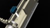
Insert the laser tube through the laser tube mounts with the laser lens facing down.

22
Laser Hybrid Instructional Image 19

Secure the top laser tube mount using one 1/4" by 1-1/2" screw, two 1/4" washers, and one 1/4" nut.

23
Laser Hybrid Instructional Image 20

Secure the bottom laser tube mount using one 1/4" by 1-1/2" screw, two 1/4" washers, and one 1/4" nut.

24
Laser Hybrid Instructional Image 21

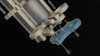
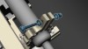
Secure the laser nozzle mount to the bottom spindle mount using two #8 x 2" screws, 2 #8 nuts, 2 1/4" washers and four #8 washers. Important Note: The washers that should be inserted with the top part of the screws are not shown in the image. Please use one 1/4" washer and one #8 washer for each screw.

25
Laser Hybrid Instructional Image 22

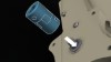
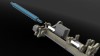
Insert the laser nozzle as shown in the image.

26
Laser Hybrid Instructional Image 23

Insert two 1/4" by 1-1/2" thumb screws into the nozzle mount with two cross dowels to adjust the laser nozzle.

27
Laser Hybrid Instructional Image 24

The thumb screws are used to secure the position of the laser nozzle for the alignment process of the laser.

28

Maintenance Instructions

Before each usage of the laser, make sure to check the laser lens in the nozzle on the bottom of the assembly. Loosen the thumb screw to free the nozzle, then separate the nozzle to expose the laser lens. Make sure the lens has been cleaned properly with a cloth so it is free of dust or any other debris.

Also make sure clean water is always used. Periodically inspect the laser mounts to make sure the glass tube is not loose.

29
--
Get Help with:
This Product
Orders
Tech Support
Sales
This Product
Order Query
Tech Support
Sales
Not logged in. Log In Register
Track Order(s)
View Order(s)
I Want to Schecule a One-On-One Paid Tech Support Session
Book an Appointment Pertaining to a BuildYourCNC Product (Free)
Ask a Quesion Below (Free):
Book an Appointment Pertaining Other Equipment ($60/half hour)
Book an Immedite Appointment Pertaining Other Equipment ($120/half hour)
Ask a Quesion Below (Free):
Waiting for response... I may not answer immediately, but I was notified on my cellular phone so my response is forthcoming. If I don't respond immediately, you can always go to the [My Account] page to see all of our chats at any time.