Instructions
If you purchased the kit that contains mounts for a spindle, please follow the pictorial steps below. For kits that contain the mounts for the Porter Cable (3.5 inch diameter router housing), please follow the video assembly instructions near the bottom of this page.
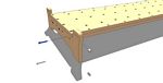
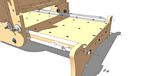
Fasten the table surface to one of the table ends. Use four (4) 1/4 x 1-1/2 inch screws and cross dowel nuts. Keep these screws loosely fastened.
Fasten the other table end using four (4) 1/4 x 1-1/2 inch screws and cross dowel nuts. Keep the screw loosely fastened.
Add the first of three under-table supports. Use eleven (11) 1/4 x 1-1/2 inch screws and cross dowel nuts. Keep all of the screws loosely fastened.

Use one (1) 1/4 x 1-1/2 inch screw and cross dowel nut to fasten the table end to the first under support piece. Keep this loosely fastened.
Use one (1) 1/4 x 1-1/2 inch screw and cross dowel nut to fasten the opposite table end to the first under support piece. Keep this loosely fastened.
Add the second of the three under-table supports. Use eleven (11) 1/4 x 1-1/2 inch screws and cross dowel nuts. Keep all of the screws loosely fastened.
Use one (1) 1/4 x 1-1/2 inch screw and cross dowel nut to fasten the table end to the second under support piece. Keep this loosely fastened.
Use one (1) 1/4 x 1-1/2 inch screw and cross dowel nut to fasten the opposite table end to the second under support piece. Keep this loosely fastened.
Add the third of the three under-table supports. Use eleven (11) 1/4 x 1-1/2 screws and cross dowel nuts. Keep all of the screws loosely fastened.
Use one (1) 1/4 x 1-1/2 inch screw and cross dowel nut to fasten the table end to the third under support piece. Keep this loosely fastened.

Use one (1) 1/4 x 1-1/2 inch screw and cross dowel nut to fasten the opposite table end to the third under table support piece. Tighten this and all of the other screws for the table supports and table ends from the previous steps.
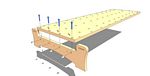
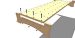
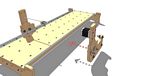
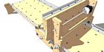
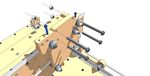
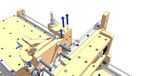
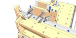
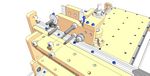
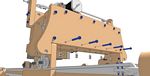
Take two (2) of the X-axis rails (longer rails), ten (10) 1/4 x 1-1/2 inch screws and ten (10) 1/4 inch nuts; fasten the rails onto the first side of the table (above and below) using the screws (inserted from the top so the heads of the screws are oriented at the top of the table) and nuts. Tighten the screws only slightly so the rails can move horizontally, but not tip. This will allow the rails to be adjusted and tightened once the gantry is assembled and the gantry can auto correct the rail position.
Take two (2) of the X-axis rails (longer rails), ten (10) 1/4 x 1-1/2 inch screws and ten (10) 1/4 inch nuts; fasten the rails onto the first side of the table (above and below) using the screws (inserted from the top so the heads of the screws are oriented at the top of the table) and nuts. Tighten the screws only slightly so the rails can move horizontally, but not tip. This will allow the rails to be adjusted and tightened once the gantry is assembled and the gantry can auto correct the rail position.

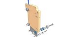
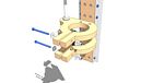
Insert one (1) 1/4 inch ID (inside diameter) bearing into the bearing seat in the shaft end gantry side. The diameter of the seat is very close to the outside diameter of the bearing, so this process may require a rubber or wood mallet to nudge the bearing into this seat.
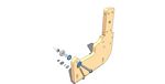
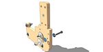
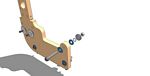
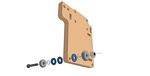
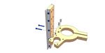
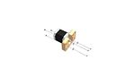
With one (1) 3/8 x 2 inch screw, one (1) v-groove bearing, two (2) large 3/8 inch washers, one (1) thin 3/8 inch washer, one (1) 3/8 inch nut, assemble the components as shown in the illustration. It is very important that the thin washer is between the v-groove bearing and large washer otherwise the outer race of the v-groove bearing will rub against the washer and the v-groove bearing will not turn.

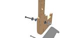
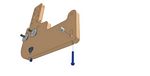
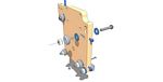
Insert one (1) 1/4 x 1-1/2 inch screw and cross dowel nut into the shaft end gantry side. Turn the screw so that only a few threads of the screw is driven into the cross dowel nut. This will provide enough space for the upcoming v-groove assembly to be added.

With one (1) 3/8 x 2 inch screw, one (1) v-groove bearing, two (2) large 3/8 inch washers, one (1) thin 3/8 inch washer, one (1) 3/8 inch nut, assemble the components as shown in the illustration making sure that the assembly is moved to the lower portion of the opening. Make sure the assembly is snug but not tight. This will enable the assembly to move up and down within this opening. It is very important that the thin washer is between the v-groove bearing and large washer otherwise the outer race of the v-groove bearing will rub against the washer and the v-groove bearing will not turn.

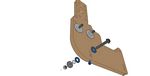
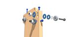
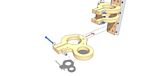
With one (1) 3/8 x 3 inch screw, one (1) v-groove bearing, two (2) large 3/8 inch washers, two (2) thin 3/8 inch washer, one (1) #25 Idler Sprocket, and one (1) 3/8 inch nut, assemble the components as shown in the illustration. It is very important that the thin washer is between the v-groove bearing and large washer and another thin washer is between the idler sprocket and the large washer otherwise the outer race of the v-groove bearing and/or the outer race of the idler sprocket will rub against the washer and the bearing will not turn.
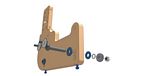
With one (1) 3/8 x 2 inch screw, two (2) large 3/8 inch washers, one (1) thin 3/8 inch washer, one (1) #25 Idler Sprocket, and one (1) 3/8 inch nut, assemble the components as shown in the illustration. It is very important that the thin washer is between the idler sprocket and the large washer otherwise the outer race of the idler sprocket will rub against the washer and the sprocket will not turn.
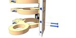
Insert one (1) 1/4 x 1-1/2 inch screw and cross dowel nut into the motor end gantry side. Turn the screw so that only a few threads of the screw is driven into the cross dowel nut. This will provide enough space for the upcoming v-groove assembly to be added.
With one (1) 3/8 x 2 inch screw, one (1) v-groove bearing, two (2) large 3/8 inch washers, one (1) thin 3/8 inch washer, one (1) 3/8 inch nut, assemble the components as shown in the illustration making sure that the assembly is moved to the lower portion of the opening. Make sure the assembly is snug but not tight. This will enable the assembly to move up and down within this opening. It is very important that the thin washer is between the v-groove bearing and large washer otherwise the outer race of the v-groove bearing will rub against the washer and the v-groove bearing will not turn.
With one (1) 3/8 x 2 inch screw, one (1) v-groove bearing, two (2) large 3/8 inch washers, one (1) thin 3/8 inch washer, one (1) 3/8 inch nut, assemble the components as shown in the illustration. It is very important that the thin washer is between the v-groove bearing and large washer otherwise the outer race of the v-groove bearing will rub against the washer and the v-groove bearing will not turn.
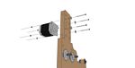
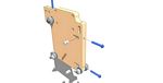
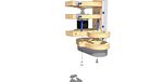
With four (4) #8 nuts, four (4) #8 washers, four (4) #8 x 1-1/2 inch screws and one (1) stepper motor, fasten the motor to the motor end gantry side using the four (4) holes provided on the gantry side. the large hole is provided so the circular motor flange protrusion can fit allowing the motor to seat flat against the gantry side. Note the orientation of the gantry side as the motor will be fastened to the same side that the v-groove bearings are located.
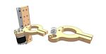
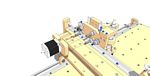
Insert the 1/4 inch shaft into the shaft end gantry side. Slide the coupling (coupler) onto the shaft at the position shown in the illustration. Take both gantries and attach them to the x-axis rails. To tighten the v-groove bearings onto the rails, tighten the adjustment screws located at the bottom of the gantry sides. Do not over tighten these screws as the rails can be damaged as a result. Very weak finger tightening is sufficient.
Move the gantry sides so that they are aligned side by side. Slide the rigid coupling (coupler) so that the coupling covers both the motor shaft and the extending shaft evenly. Do not tighten the rigid coupling until the gantry is completely assembled and the rails are aligned and adjusted with respect to the gantry v-groove bearings.
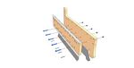
Assemble the y-axis rail and rail support piece using six (6) 1/4 x 1 inch screws and cross dowels. Make sure the rail support and rail are positioned on a flat surface as shown. The rail will not be flush with the rail support piece. The construction of the rail and support is done in this fashion so that the two rails will be parallel once the next rail is added. Keep the screws loose until both rails are added to the support piece and is resting on a flat surface. Orient the Y-axis support piece as shown (the counter-bored side faces down).
Assemble the second y-axis rail and rail support piece using six (6) 1/4 x 1 inch screws and cross dowels. Make sure the rail support and rail are positioned on a flat surface as shown. Once the rail is fastened, while resting on a flat surface, tighten all of the screws on both first and second rail.
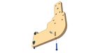
Take the assembled y-axis rails and support and fasten this assembly to the gantry front with five (5) 1/4 x 1-1/2 inch screws and 1/4 inch nuts. Note the orientation of the gantry front.
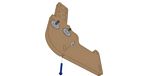
Attach the gantry bottom to the gantry front using five (5) 1/4 x 1-1/2" screws and cross dowels.
Move the previous assembly of the gantry front/bottom and rail assembly to the ledge of the gantry sides.

Loosely fasten the right side of the gantry front to the shaft end gantry side using one (1) 1/4 x 1-1/2 inch screw and cross dowel nut.

Loosely fasten the left side of the gantry front to the motor end gantry side using one (1) 1/4 x 1-1/2 inch screw and cross dowel nut.
Insert two (2) cross dowel nuts into the shaft end gantry side as shown.

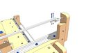
Insert one (1) 1/4 x 2 inch screw in the top slot of the y-axis rail support and drive into the top cross dowel from the previous step. Insert one (1) 1/4 x 1-1/2 inch screw in the lower slot of the gantry front piece and drive into the lower cross dowel from the previous step.
Insert two (2) cross dowel nuts into the motor end gantry side as shown.

Insert one (1) 1/4 x 2 inch through the slot located on the y-axis rail support and drive into the cross dowel from the previous step. Insert one (1) 1/2 x 1-1/2 inch screw into the lower slot located on the gantry front and drive into the cross dowel from the previous step. At the completion of this step, run the gantry up and down the x-axis rails to work the rails into a position that matches the width of the gantry. Move the gantry to the rear of the table and tighten the first screw holding the x-axis rails on both sides. Then roll the gantry to the opposite end of the table and tighten the end screws holding the x-axis rails. Roll the gantry to the midpoint of the table and tighten the x-axis screws at this position. finally, tighten all of the remaining x-axis rail screws.
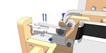
Slide the drive sprocket on the stepper motor shaft. Align the drive sprocket with the lower idler sprockets as close as possible so the chain will enter and exit the sprockets harmoniously.
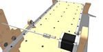
Fasten one (1) eye bolt, one 1/4 inch washer and one (1) 1/4 inch nut to the left side of the front table end as shown. Only drive the nut a few turns so there will be enough thread to tension the roller chain.
Fasten one (1) eye bolt, one 1/4 inch washer and one (1) 1/4 inch nut to the left side of the rear table end as shown. Only drive the nut a few turns so there will be enough thread to tension the roller chain.
Route the roller chain from one eye bolt, under the idler sprockets, over the drive sprocket and ending at the eye bolt at the other end along the left side of the machine.
Curl the roller chain into the eye of the eye bolt at the front left table end. Use two (2) #4 screws and #4 nuts to secure the curled roller chain to the eye bolt. The #4 screws will fit between the roller chain link plates.
Curl the roller chain into the eye of the eye bolt at the rear left table end. Use two (2) #4 screws and #4 nuts to secure the curled roller chain to the eye bolt. The #4 screws will fit between the roller chain link plates.
Slide the drive sprocket on the shaft end. Align the drive sprocket with the lower idler sprockets as close as possible so the chain will enter and exit the sprockets harmoniously.
Fasten one (1) eye bolt, one 1/4 inch washer and one (1) 1/4 inch nut to the right side of the front table end as shown. Only drive the nut a few turns so there will be enough thread to tension the roller chain.
Fasten one (1) eye bolt, one 1/4 inch washer and one (1) 1/4 inch nut to the right side of the rear table end as shown. Only drive the nut a few turns so there will be enough thread to tension the roller chain.
Route the roller chain from one eye bolt, under the idler sprockets, over the drive sprocket and ending at the eye bolt at the other end along the right side of the machine.
Curl the roller chain into the eye of the eye bolt at the front right table end. Use two (2) #4 screws and #4 nuts to secure the curled roller chain to the eye bolt. The #4 screws will fit between the roller chain link plates.
Curl the roller chain into the eye of the eye bolt at the rear right table end. Use two (2) #4 screws and #4 nuts to secure the curled roller chain to the eye bolt. The #4 screws will fit between the roller chain link plates.
Fasten the top of the y-axis rail support and gantry top to the gantry front using five (5) 1/4 x 2 inch screws and cross dowels.
With the Z/Y plate in hand, assemble the Y-axis bottom left v-groove assembly in the lower left hand hole as shown. Note the orientation of the Z/Y plate and the side that the screw musts be inserted into the assembly. Use one (1) 3/8 x 3 inch screw, two (2) v-groove bearings, two (2) 3/8 inch thin washers, three (3) large 3/8 inch washers and one (1) 3/8 inch nut. Make sure the thin washer is positioned between the v-groove bearing and the large washer so the outer race does not rub against the large washer. The two large abutting washers are needed to allow for space between the y-axis rail and the screw heads that will be added in later steps.

Insert the 1/4 x 3 inch adjustment screw and the cross dowel into the Z/Y plate as shown. Only drive the screw into the cross dowel half way so the v-groove bearing assembly can be placed into the space below.

Assemble the Y-axis top left v-groove and Z-axis top left assembly in the upper left hand slot as shown. Note the orientation of the Z/Y plate and the side that the screw musts be inserted into the assembly. Use one (1) 3/8 x 3 inch screw, two (2) v-groove bearings, two (2) 3/8 inch thin washers, three (3) large 3/8 inch washers and one (1) 3/8 inch nut. Make sure the thin washer is positioned between the v-groove bearing and the large washer so the outer race does not rub against the large washer. The two large abutting washers are needed to allow for space between the y-axis rail and the screw heads that will be added in later steps.
Assemble the Y-axis bottom right v-groove assembly in the lower right hand hole as shown. Note the orientation of the Z/Y plate and the side that the screw musts be inserted into the assembly. Use one (1) 3/8 x 2 inch screw, one (1) v-groove bearing, one (1) 3/8 inch thin washer, three (3) large 3/8 inch washers and one (1) 3/8 inch nut. Make sure the thin washer is positioned between the v-groove bearing and the large washer so the outer race does not rub against the large washer. The two large abutting washers are needed to allow for space between the y-axis rail and the screw heads that will be added in later steps.
Insert two (2) 1/4 x 1-1/2 inch adjustment screws and cross dowels into the Z/Y plate as shown. Only drive the screws into the cross dowel half way so the v-groove bearing assembly can be placed into the slotted space.

Assemble the Z-axis bottom right v-groove assembly in the lower right hand slot as shown. Note the orientation of the Z/Y plate and the side that the screw must be inserted into the assembly. Use one (1) 3/8 x 2 inch screw, one (1) v-groove bearing, one (1) 3/8 inch thin washer, two (2) large 3/8 inch washers and one (1) 3/8 inch nut. Make sure the thin washer is positioned between the v-groove bearing and the large washer so the outer race does not rub against the large washer.
Assemble the Z-axis top right v-groove assembly in the lower right hand slot as shown. Note the orientation of the Z/Y plate and the side that the screw must be inserted into the assembly. Use one (1) 3/8 x 2 inch screw, one (1) v-groove bearing, one (1) 3/8 inch thin washer, two (2) large 3/8 inch washers and one (1) 3/8 inch nut. Make sure the thin washer is positioned between the v-groove bearing and the large washer so the outer race does not rub against the large washer.

Insert the 1/4 x 1-1/2 inch adjustment screw and the cross dowel into the Z/Y plate as shown. Only drive the screw into the cross dowel half way so the v-groove bearing assembly can be placed into the space below.
Assemble the Y-axis top right v-groove assembly in the top right slot as shown. Note the orientation of the Z/Y plate and the side that the screw must be inserted into the assembly. Use one (1) 3/8 x 2 inch screw, one (1) v-groove bearing, one (1) 3/8 inch thin washer, three (3) large 3/8 inch washers and one (1) 3/8 inch nut. Make sure the thin washer is positioned between the v-groove bearing and the large washer so the outer race does not rub against the large washer.
Slide the Z/Y Plate Assembly onto the Y-axis rails as shown. Make sure the top adjustment screws are loose so the v-groove bearings have sufficient distance from each other to fit on the y-axis rails. Once on the rails, gently tighten the adjustment screws so the top v-groove bearings are compressed against the rails snugly. The plate assembly should be able to easily run back and forth along the y-axis rails with no play.
Insert four (4) 3/8 x 3 inch screws into the holes shown on the Z/Y plate and adhere these screws into position with four (4) 3/8 inch nuts. The holes may be slightly smaller than the major screw diameter, so the screws may need to be driven into these holes.
Fasten Z-axis right hand rail to the Z-axis rail support piece. Use five (5) 1/4 x 1 inch screws and cross dowel nuts. Note the orientation of the z-axis rail support piece.
Fasten Z-axis left hand rail to the Z-axis rail support piece. Use five (5) 1/4 x 1 inch screws and cross dowel nuts. Note the orientation of the z-axis rail support piece.
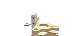
Fasten the middle spindle mount to the z-axis rail support piece. Note the orientation of the rail support. Use two (2) 1/4 x 1-1/2 inch screws and cross dowel nuts. If the router mount was selected and not a spindle mount, this will serve as the top router mount.

Secure the Z-axis stepper motor to the mount as shown. Use four (4) #8 x 1-1/2 inch screws, four (4) #8 washers and four (4) #8 nuts. Do not tighten completely as the motor position will need to be adjusted to align with the coupling (coupler) and lead screw assembly.

Slide the flexible coupler assembly which consists of one (1) 1/4 inch ID (inside diameter) coupling hub, one (1) coupling spider (rubber component) and one (1) 1/2 inch ID coupling hub. Do not tighten the set screws until the other components for the lead screw are assembled.
Insert one (1) 1/2 inch ID (inside diameter) bearing into the bearing seat of the top spindle mount. Rest one (1) 1/2 inch ID thin washer on top of the bearing to protect the outer race of the bearing from interfering with the upcoming collar.. If the router mount was selected, this piece will not appear as a mount, but appear as a piece with a bearing seat with two cross dowel holes.
Fasten the top spindle mount to the Z-axis rail support as shown using two (2) 1/4 x 1-1/2 inch screws and cross dowels.
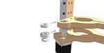
In preparation for mounting the lead screw, position one (1) 1/2 inch ID (inside diameter), one (1) 1/2 inch ID bearing and one (1) 1/2 inch ID bearing as shown. The collar will rest on top of the top bearing/washer that is seated in the top spindle mount. The bearing and washer below will rest on top of the flexible coupler.

Insert the lead screw into the anti-backlash nut as shown. It is critical that the lead screw is driven into the anti-backlash nut from the top of the nut and not from the bottom of the nut. The alignment of the lead screw will be more successful if installed in this way. The anti-backlash assembly has a nut that is flexible, a spring that pushes a bushing up to squeeze the flexible portion of the nut. Important: depress the bushing of the anti-backlash nut downward so the flexible portion of the nut is opened enough to allow the screw to be inserted relatively easily. Make sure the screw is as aligned with the nut as well as possible to prevent the thread of the lead screw from catching the incorrect thread in the nut.

Insert the lead screw through the anti-backlash nut support piece and then through the collar, washer, bearings and into the flexible coupling. Note the orientation of the anti-backlash nut support piece. Tighten the flexible coupling set screws at the motor shaft hub and the lead screw hub.
Insert the spindle/router mount tightening screws. Use two (2) 1/4 x 3 inch screws, four (4) 1/4 ID (inside diameter) washers and two (2) 1/4 inch nuts.
Add the router/spindle tightening hardware one (1) 1/4 x 3 inch screw, two (2) 1/4 ID (inside diameter) washers and one (1) 1/4 inch nut to the lower spindle/router mount. Get this assembly ready for mounting to the z-axis assembly.
Fasten the lower spindle/router mount to the z-axis assembly. Use two (2) 1/4 x 1-1/2 inch screw and cross dowels.
Insert two (2) 1/4 inch nut inserts into the bottom of the dust shoe. Insert the two (2) 1/4 inch thumb screws into the top of the lower spindle/router mount. Drive the thumb screws into the nut inserts as shown.

Slide the complete z-axis assembly between the z-z-axis v-groove bearings as shown. Make sure the v-groove adjustment screws are driven back as far as possible so the v-grove bearings are at the maximum distance apart. Once the assembly is completely between the bearings, gently tighten the adjustment screws. Do not over tighten these adjustment screws as the rails will be damaged. The adjustment screws that push the bearings toward the rail contains a lot of torque so proceed with caution.
Fasten the Z-axis anti-backlash nut support piece to the Z/Y plate as shown. Use two (2) 1/4 x 1-1/2 inch screws and cross dowels.
Loosely fasten the anti-backlash nut to the anti-backlash nut support piece with two (2) #8 x 1-1/2 inch screws, two (2) #8 washers and two (2) #8 nuts. Keep an eye on the vertical alignment of the lead screw assembly. The lead screw should be as parallel as possible with the z-axis. To insure this, after loosely fastening the hardware mentioned for this step, by hand, drive the lead screw as far up the anti-backlash nut as possible where the collar will almost touch the anti-backlash nut support. Check the vertical level of the lead screw above the anti-backlash nut with respect to the z-axis assembly and tighten the #8 hardware.
Prepare the Y-axis right chain mount for fastening as shown. Note the orientation of the mount.
Using one (1) 1/4 x 1-1/2 inch screw, one (1) 1/4 washer and one (1) cross dowel, fasten the left side of the y-axis right chain mount. Keep this loosely fastened so the height can be adjusted later.
Fasten the remaining two (2) 1/4 x 1-1/2 inch screws, two (2) 1/4 inch washers and cross dowels for the Y-axis right chain mount. Keep these loosely fastened for height adjustment later.
Insert one (1) eye bolt, one (1) 1/4 inch washer and one (1) 1/4 nut as shown. Drive the eye bolt into the nut only slightly so there will be sufficient threads available to tension the roller chain.
Fasten the left side of the Y-axis left chain mount using two (2) 1/4 x 1-1/2 inch screws, two (2) 1/4 inch washers and two (2) cross dowels. Keep these loosely fastened for later height adjustment.

Finish loosely fastening the Y-axis left chain mount with one (1) 1/4 x 1-1/2 inch screw, one (1) 1/4 washer and one (1) cross dowel.
Insert one (1) eye bolt, one (1) 1/4 inch washer and one (1) 1/4 nut as shown. Drive the eye bolt into the nut only slightly so there will be sufficient threads available to tension the roller chain.
Slide one (1) #25 idler sprocket onto the 3/8 inch screw as shown. This idler sprocket will not be fastened into place as this sprocket will be free to move side to side so chain alignment can always be autocorrected.
Drive three (3) 3/8 inch nuts to the 3/8 inch screws as shown. Drive these nuts all the way to the existing nuts, but do not tighten as they will be used to tighten against the motor mount support.

Drive one (1) #8 nut insert into the Y-axis motor mount support as shown. Take the motor and one (1) #8 x 1 inch screw and fasten the motor in place. Keep this loosely tightened until all of the other mounting screws are fastened.
Fasten the remaining three (3) #8 x 1-1/2 inch screws, three (3) #8 washers and three (3) #8 nuts as shown. Note the direction that the screws are inserted and the placement of the nuts.

Insert the drive sprocket to the shaft of the Y-axis motor. Keep the set screws loose until the mount is fastened and aligned on the machine so that the drive sprocket can be aligned with the idler sprocket and chain.
Slide the motor and motor mount assembly onto the machine as shown. Try to keep the motor mount as parallel as possible to the Z/Y plate in both top and side perspectives.
Complete the installation of the Y-axis motor mount assembly by adding four (4) 3/8 inch nuts against the back of the motor mount. Tighten the nuts from the previous step against the mount keeping the mount parallel to the Z/Y plate. Bring the mount assembly as close as possible to the Z/Y plate without binding the idler sprocket.
Route the Y-axis roller chain over the top of the idler sprocket and then back around to the drive sprocket as shown.
Curl the roller chain into the eye of the eye bolt at the high end of the Y-axis. Use two (2) #4 screws and #4 nuts to secure the curled roller chain to the eye bolt. The #4 screws will fit between the roller chain link plates.
Curl the roller chain into the eye of the eye bolt at the low end of the Y-axis. Use two (2) #4 screws and #4 nuts to secure the curled roller chain to the eye bolt. The #4 screws will fit between the roller chain link plates.

Insert an end mill into the spindle or router. Slide the spindle or router into the mounts and tighten the mounts. Keep an eye on where the end mill is located during this process. If the z-axis assembly is low, then there is a possibility that the end mill will hit the table damaging the table, or the end mill.
Tighten all of the components within the gantry cavity including the rigid coupling, any hardware associated with the gantry. Run the motor wires out of the top corner of the gantry and attach the gantry back. Clip or tape the motor wires so the motor wires don't find their way back into the gantry cavity. To begin attaching the gantry back, use five (5) 1/4 x 1-1/2 inch screws and cross dowels. Important: Keep these screws loose and to assist the cross dowel position, use a magnet above the cross dowel while driving the screw into the cross dowel. If a cross dowel falls into the gantry cavity, the machine can be tipped so the cross dowel can roll out of the cavity.
Fasten the gantry back at the left side of the machine using two (2) 1/4 x 1-1/2 inch screws and cross dowels. Keep these loosely fastened.
Fasten the gantry back at the right side of the machine using two (2) 1/4 x 1-1/2 inch screws and cross dowels. Keep these loosely fastened.

Fasten the gantry back to the right gantry side as shown. Use one (1) 1/4 x 1-1/2 inch screw and cross dowel nut.
Fasten the gantry back to the right gantry side as shown. Use one (1) 1/4 x 1-1/2 inch screw and cross dowel nut.
Loosely fasten the final five (5) 1/4 x 1-1/2 inch screws and cross dowels. Once the screws are all loosely fastened, tighten all of the screws associated with the steps for the gantry back. This is a good time to check the entire machine for any play and adjust as necessary. Once this is complete, tension the roller chain for the X-axis and Y-axis. The deflection for the roller chain should not be more than 1/2 inch with light pressure pushing down or raising the roller chain from a midpoint. Check the machine for square by moving the axes along a square and adjust the eye bolts as necessary to get the machine perfectly square with respect to the X and Y axes.
Congratulations! You have just completed assembling a very complex machine and this is an exceptional achievement. To connect and wire the electronics, please follow the videos for wiring the electronics here.
The following videos provide a bit of information on the machine and also serve as the assembly instructions for the initial version of the machine. It is recommended that all of these videos be viewed prior to purchasing and/or assembling the machine. This kit can be assembled by customers of varying levels of ability and this kit will take a minimum of 4 hours of total assembly (not including electronics) with a moderate level of experience (experience relates to general handyman skills of putting together mechanical fasteners, handling general tools, and understanding the ins-and-outs of parts and tools shown in the video).
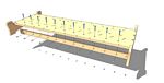
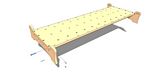
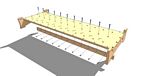
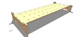
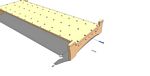
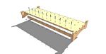
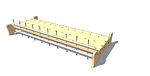
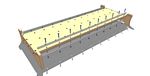
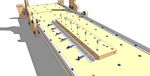
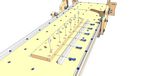
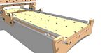
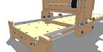
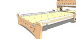
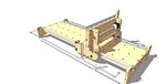
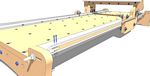
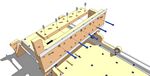
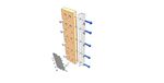
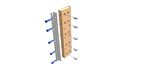
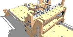
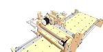
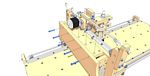
Assembling the table ribs, table ends and x-axis rails. The table is assembled which includes the bed of the table, the ribs underneath to reinforce the bed, the ends of the table and the x-axis rails on both sides of the table.
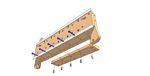
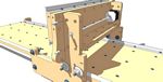
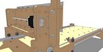
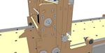
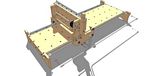
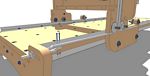
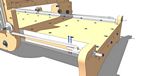
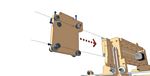
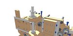
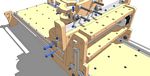
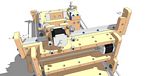
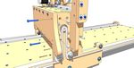
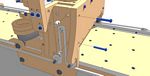
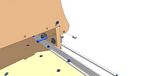
Attaching the Gantry Sides to the Table Rails. The gantry sides are outfitted with the v-groove bearings and sprockets for attaching onto the table rails.
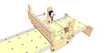
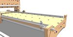
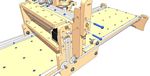
Assembling the y-axis rails and gantry bridge. The gantry bridge is attached to the y-axis rail support and the rails are installed. The x-axis rails are also tightened.
Attaching the Gantry Supports and Preparing the Z/Y Plate. The top and bottom gantry supports are attached to the back of the front gantry bridge. The Z?Y plate is prepared by fastening the v-groove bearings that will ride on the y-axis rails and hold the z-axis rail assembly.
Adding the Nut Mount, Y-axis Motor Mount and Chain Mounts. The anti-backlash nut mount is attached to the Z/Y Plate, the Y-axis Motor Mount and Y-Axis Idler
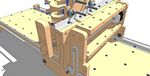
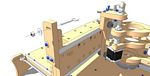
Putting Together the Z-Axis Assembly and Attaching it to the Z/Y Plate. All of the parts that make up the z-axis assembly including rail support, motor mount and router mounts are assembled together. The assembly is then put between the v-groove bearings for the z-axis and the lead screw assembly is added.
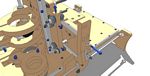
Mounting the X and Y motors and Roller Chains. The remaining motors and related mechanics will be added to the machine. This includes, mounting the motors X and Y motors, adding the drive sprocket to each of the motors, adding the roller chain (2 for the x axis and 1 for the y axis), and adding the shaft extension to the back of the X axis motor to hold the drive sprocket at the other end.
Adding the Back-Plate. The back-plate of the gantry is added to the machine.
Additional Information:
If you find that the sprockets are slipping on the x-axis 1/4" rods, make sure to file a flat so the set screw can seat well.